Key details for this exam, checked against the published exam outline
Each question shows the correct answer and an explanation of why it is right
Choose the correct answer:
Consider the following diagram fragment:
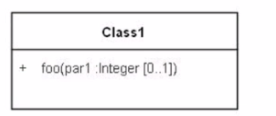
Which statement is correct about the parameter part?
In UML, when a class diagram shows an operation with a parameter that has a multiplicity of [0..1], it indicates that the parameter is optional. The range [0..1] means that the parameter can have 0 or 1 occurrence. This does not mean it accepts a collection, nor does it specify the values it accepts (it specifies how many times the parameter can occur).
The correct interpretation of the parameter par1 : Integer [0..1] is:
A . It is optional.
B is incorrect because the multiplicity [0..1] does not mean a collection of items; rather, it signifies that the parameter can be omitted or present, but not multiple times. C is incorrect because the multiplicity [0..1] does not constrain the values to 0 or 1; it refers to the number of instances of the parameter. D is incorrect because [0..1] is not a range of values but a range of occurrences or instances of the parameter.
Therefore, the correct answer is:
A . It is optional.
Choose the correct answer:
In UML modeling, what is a Constraint?
In UML modeling, a constraint is defined as:
A . a condition that must be satisfied when it is evaluated
A constraint is a semantic condition or restriction expressed in natural language text or a machine-readable language for expressing constraints, such as OCL (Object Constraint Language). Constraints specify invariants that must hold for the system being modeled at all times. This means that whenever the constraint is evaluated, the condition it expresses must be satisfied (UML 2.5 specification, section 7.9).
The other options do not accurately define what a constraint is in the context of UML:
B . A condition that should be met depending on system operation -- This is not precise as constraints are not optional and do not depend on system operation; they are always applicable.
C . A condition that causes the state of the objects to change over time -- This describes a side effect, which is not the purpose of a constraint. A constraint is a condition that must always be met, not something that induces change.
D . A condition that constrains what can or cannot be put in a class diagram -- This is too broad and imprecise. Constraints apply to elements within the class diagram and are not about the content of the diagram itself.
Choose the correct answer:
What is the name of the property represented by the leftmost lifeline in the following diagram?
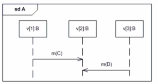
In a UML sequence diagram, a lifeline is identified by a box at the top of a dashed line that represents the presence of an individual participant in an interaction. The box contains the name of the lifeline, and optionally, it can include the object name and its classifier type.
In the diagram provided, the leftmost lifeline is labeled v[1]:B, which denotes an instance named v[1] of the classifier B. The name of the property that the lifeline represents is v[1], as B is the type of the object that the lifeline represents, and m represents a message, not a lifeline.
Therefore, the correct answer is:
A . v[1]
Choose the correct answer:
Consider the following invalid state machine fragment:
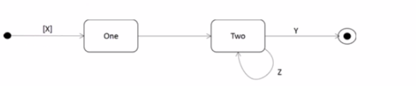
Why is the diagram invalid?
The provided image depicts a state machine fragment containing an invalid transition. The state machine has a single state labeled 'S1' with an incoming and outgoing transition labeled 'e'.
According to the UML 2 Foundation documents, a transition in a state machine cannot originate from and target the same state. This type of loopback transition within a single state is not permitted.
Here's a breakdown of why other options are incorrect:
Option A (A transition requires a trigger or guard) is not necessarily true. Transitions can exist without explicit triggers or guards, although their presence is often recommended for clarity and modeling complex behavior.
Option B (A guard condition is not allowed on the initial transition) is valid. Guard conditions are indeed not allowed on the initial transition of a state machine, but the issue in the diagram is the loopback, not the presence or absence of a guard.
Option C (A trigger is not allowed on the transition to the final state) is not always true. Final states can have outgoing transitions with triggers under specific circumstances (e.g., for hierarchical state machines). However, the error here concerns the loopback nature of the transition.
Choose the correct answer: Consider the following interaction diagram.
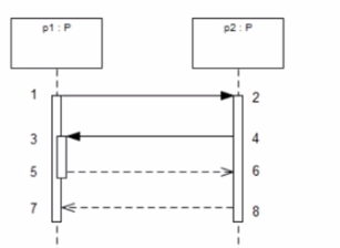
Which number pair represents the start and end of an execution specification?
In UML sequence diagrams, an execution specification is represented by a thin rectangle along a lifeline. It shows where in time the execution takes place, starting with the initiation of an operation or process and ending when that process is complete.
In the interaction diagram provided, we can see an execution specification on the lifeline p1: P that starts after the message corresponding to point 3 is received and ends just before the message corresponding to point 5 is sent. This means the execution specification is bracketed by points 3 and 5.
Points 1 and 2 represent message sends, 1 and 4 could represent a message send and receive for the same message, which doesn't typically represent the full execution specification. Points 2 and 3 don't represent a logical start and end of an execution specification because they're on different lifelines.
Therefore, the correct answer is:
D . 3, 5
Choose the correct answer:
Which element in the following sequence diagram could correspond to a signal?
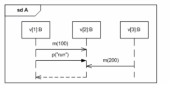
In UML sequence diagrams, a signal is typically represented as an asynchronous message without a return value. Asynchronous messages are often denoted with an open arrowhead, and they can represent the sending of a signal.
Looking at the diagram provided, 'p' is sent from 'v2[C]' to 'v3[B]' with an open arrowhead, which indicates that it is an asynchronous message. This fits the common representation of a signal, as it does not expect a response.
'A', 'B', and 'C' do not represent signals in the context of a sequence diagram: A) 'v' is not shown in the diagram; it might refer to a lifeline, which is not a signal. B) 'B' refers to a class or object type and not a message or signal. C) 'm' is represented as a synchronous message (as it has a return arrow), which is not typical for signals.
Therefore, the correct answer is:
D . p
Choose the correct answer:
Which statement is true about the following diagram?
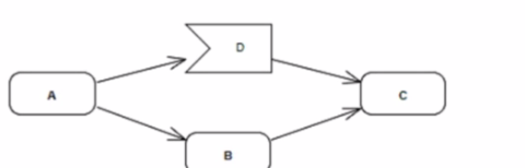
The diagram likely represents a UML activity diagram, which is used to model the workflow of a system. The correct answer is D because it reflects the behavior of decision nodes and concurrent flows in UML activity diagrams.
In UML, when an activity reaches a decision node (depicted as a diamond), it chooses one among several alternative flows. In this case, after the completion of action A, the flow must decide between B or D, but not both, which is a fundamental aspect of decision nodes in UML. This is supported by the UML 2.5 specification, which states that a decision node routes tokens to one of the available outgoing edges based on the conditions evaluated at runtime, ensuring that only one path is taken.
Furthermore, the UML specification explains that the notation for decision nodes and the semantics of token flows are such that they support the modeling of conditional and concurrent behaviors within an activity. This is essential for accurately capturing the logic of complex systems and their operations.
For a more in-depth understanding, you can refer to the UML 2.5.1 specification provided by the Object Management Group (OMG), which details the notation and semantics of activity diagrams, including decision nodes and flows. Additionally, studying the official OMG UML 2 Certification Guide can provide further clarification on these concepts.
8 domains from the OMG OMG-OCUP2-FOUND100 exam outline, with approximate weightings. Every sample question above is tagged with the domain it comes from
This section deals with modeling the workflow of a system's operations and activities. Activity diagrams show the sequence of steps in a process and the conditions that trigger each step.
Sample question from this domain above: Q7
In this section, candidates are tested on how objects interact in a sequence of events. Sequence diagrams show messages exchanged between objects and the temporal order of those interactions.
This section deals with the explanation of the goal and benefits of using UML for software modeling. It covers why certain domains use modeling and what benefits they derive from it.
Sample question from this domain above: Q2
This section explains the object states and the transitions between those states. State machine diagrams show different states, the events that trigger transitions, and the actions that occur.
Sample question from this domain above: Q4
This section deals with a snapshot of the system at a specific point in time. Object diagrams show instances of classes and their relationships in a particular state.
In this section, knowledge is tested regarding organizing and grouping of components of a system into packages. Package diagrams show how model elements are organized and how dependencies exist between packages.
This section shows the functional requirements of a system through actors and their interactions. Use case diagrams depict what the system does from the perspective of external users.
This section covers the static structure of a system by defining classes, their characteristics, relationships, and attributes. Class diagrams form the backbone of object-oriented system design.
Common questions about the exam itself

