The Juniper JN0-664 exam validates your expertise in service provider routing and switching technologies. This assessment is designed for network professionals who design, deploy, and maintain carrier-grade routing and switching infrastructure using Juniper platforms. This page provides a structured study roadmap covering the core topics, question formats, and practical preparation strategies you need to pass the Service Provider Routing and Switching, Professional Exam and advance your Juniper Service Provider Routing & Switching Certification.
Use this topic map to guide your study for Juniper JN0-664 (Service Provider Routing and Switching, Professional Exam) within the Juniper Service Provider Routing & Switching Certification path.
The JN0-664 exam combines knowledge-based and scenario-driven questions to assess both foundational understanding and applied decision-making in production environments.
Questions increase in complexity as you progress, emphasizing practical troubleshooting and design reasoning over rote memorization.
Effective preparation requires a structured schedule that builds from fundamentals to integrated scenarios. Dedicate time each week to one or two topics, hands-on practice, and cumulative review to reinforce connections between routing, QoS, and VPN technologies.
Explore other Juniper certifications: view all Juniper exams.
Strengthen your preparation with up-to-date resources from validexamdumps.com. These materials align to JN0-664 and cover practical scenarios with clear explanations.
Visit the exam page to download the PDF, Online Practice Test or get Bundle Discount offer for both formats: Service Provider Routing and Switching, Professional Exam.
BGP, OSPF, and Layer 3 VPNs typically represent the largest portion of the exam, reflecting their critical role in service provider networks. However, all seven topics are tested, and weaknesses in any area can lower your overall score. Balance your study time by spending extra hours on BGP policy and VPN route filtering, while maintaining solid coverage of IS-IS, CoS, multicast, and Layer 2 VPNs.
In production, IGPs (OSPF and IS-IS) carry internal traffic and establish the underlay network, while BGP manages external routes and VPN customer prefixes. Layer 3 VPNs rely on both the IGP underlay and BGP overlays to distribute customer routes across PE routers. CoS policies then enforce SLA guarantees on the shared infrastructure. Understanding these dependencies is essential for troubleshooting end-to-end connectivity and performance issues.
Hands-on experience is highly valuable for building confidence and muscle memory. Prioritize labs for BGP policy configuration, Layer 3 VPN PE-CE setup, and CoS queue scheduling, as these directly map to exam scenarios. If access is limited, focus on reading configuration examples, interpreting command output, and mentally walking through configuration steps rather than skipping hands-on practice entirely.
Candidates often misunderstand BGP path selection rules, confuse IS-IS level hierarchies with OSPF areas, and overlook CoS interaction with MPLS EXP bits. Another frequent error is assuming Layer 3 and Layer 2 VPN technologies are interchangeable; they serve different use cases and have distinct configuration requirements. Careful reading of scenario details and review of protocol specifics during practice tests will help you avoid these pitfalls.
In your final week, take one full-length practice test under exam conditions and review every incorrect answer, even if you guessed correctly. Spend 20-30 minutes daily reviewing your weakest topics rather than re-reading entire chapters. On the day before the exam, do a light review of key terms and policy syntax, then rest well. During the exam itself, read each question carefully, flag difficult items for later review, and allocate time proportionally to question complexity.
Exhibit
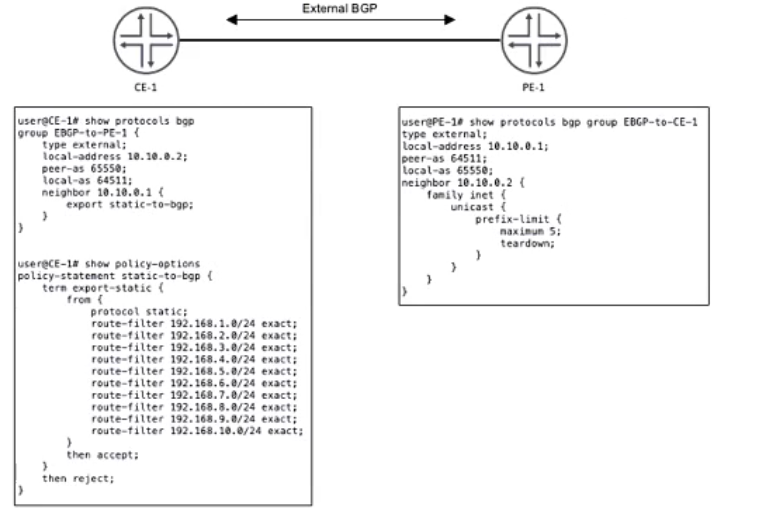
CE-1 must advertise ten subnets to PE-1 using BGP Once CE-1 starts advertising the subnets to PE-1, the BGP peering state changes to Active.
Referring to the CLI output shown in the exhibit, which statement is correct?
Analyzing the Exhibit and Understanding the Issue
The exhibit shows BGP configurations on CE-1 and PE-1, which are connected via EBGP.
CE-1 (Customer Edge)
Uses AS 64511 and establishes an EBGP session with PE-1 (AS 65550).
Configured to export 10 static routes (192.168.1.0/24 - 192.168.10.0/24) using the static-to-bgp policy.
PE-1 (Provider Edge)
Uses AS 65550 and is peering with CE-1 (AS 64511).
Configured with a prefix-limit of 5 on received routes from CE-1.
Teardown enabled, meaning if more than 5 prefixes are received, the BGP session is shut down.
Identifying the Problem
CE-1 is correctly configured with peer AS 65550, so Option B ('CE-1 is configured with an incorrect peer AS') is incorrect .
CE-1 is advertising exactly 10 static routes (as per policy).
PE-1 has a prefix-limit maximum 5 with teardown enabled.
This means that when CE-1 advertises more than 5 prefixes, PE-1 shuts down the BGP session.
BGP moves to the 'Active' state, indicating that the session has been disrupted and PE-1 is trying to re-establish the connection.
CE-1 is reachable since the session was initially established before the limit was exceeded, so Option D ('CE-1 is unreachable') is incorrect .
CE-1 is not advertising its entire routing table, only the static prefixes listed in the policy, so Option A ('CE-1 is advertising its entire routing table') is incorrect .
Correct Answer
C. The prefix limit has been reached on PE-1
Verification from Juniper Documentation
Juniper BGP Prefix Limit Documentation confirms that exceeding the prefix limit with teardown causes the BGP session to go into 'Active' state.
Juniper Troubleshooting Guide for BGP Peering Issues states that when a BGP session reaches the prefix limit and has teardown enabled, the session is terminated.
Exhibit
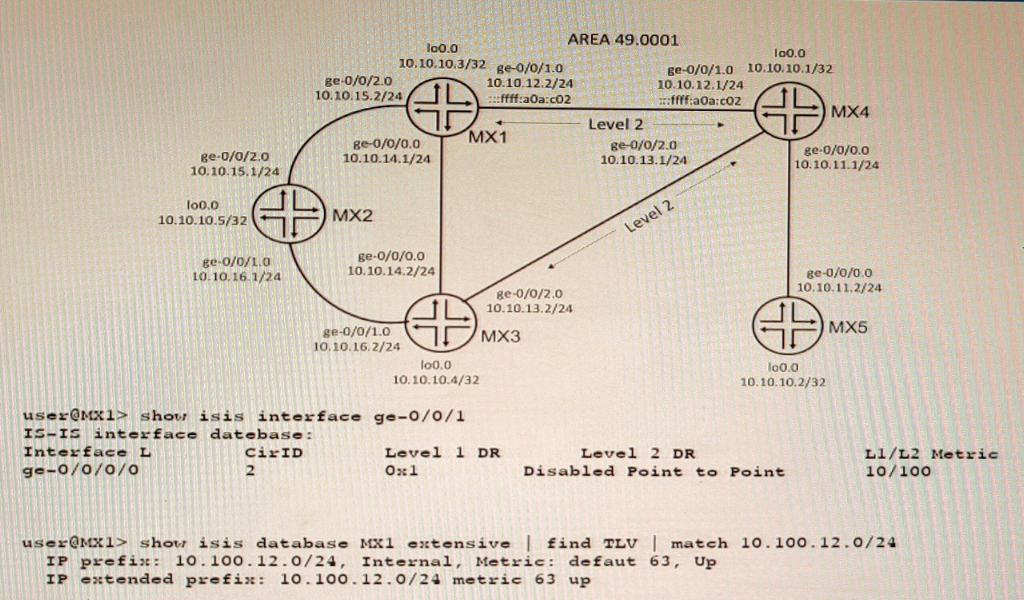
A network is using IS-IS for routing.
In this scenario, why are there two TLVs shown in the exhibit?
Exhibit
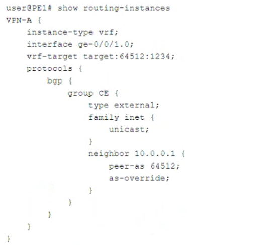
Which two statements about the configuration shown in the exhibit are correct? (Choose two.)
The provided configuration is for a routing instance named VPN-A on a Juniper PE (Provider Edge) router. Let's break it down:
Instance Type: VRF
The instance-type vrf; statement indicates that this is a Layer 3 VPN (L3VPN) using MPLS VPNs (RFC 4364 -- BGP/MPLS IP VPNs).
This confirms that Option D (A Layer 3 VPN is configured) is correct .
VRF Target and Interface Association
The vrf-target target:64512:1234; defines the route target (RT) for importing and exporting VPN routes.
The interface ge-0/0/1.0; binds this interface to the VRF.
BGP Configuration for CE (Customer Edge) Peering
The group CE section configures external BGP (EBGP) (type external;).
The neighbor 10.0.0.1 is in AS 64512 (peer-as 64512;).
The as-override; statement is used.
Evaluating the Answer Choices
Option B: 'This VPN connects customer sites that use the same AS number.'
The as-override; command allows multiple customer sites that use the same AS number (64512) to communicate over the service provider's MPLS network.
Normally, BGP prevents routes with the same AS in the AS_PATH from being accepted. The as-override feature replaces the customer's AS number with the provider's AS, ensuring proper route advertisement.
This statement is correct.
Option A: 'This VPN connects customer sites that use different AS numbers.'
If the customer sites had different AS numbers, there would be no need for as-override.
The as-override feature is specifically used when all customer sites share the same AS number, ensuring that BGP routes are accepted.
This statement is incorrect.
Option C: 'A Layer 2 VPN is configured.'
A Layer 2 VPN (L2VPN) configuration would typically use instance-type l2vpn; or EVPN/VPLS-related parameters (e.g., protocols l2vpn or protocols vpls).
Since this configuration uses instance-type vrf; and BGP with a VRF target, it is clearly a Layer 3 VPN (L3VPN).
This statement is incorrect.
Option D: 'A Layer 3 VPN is configured.'
The instance-type vrf; confirms this is an MPLS Layer 3 VPN (L3VPN).
VRFs, BGP, and route targets (vrf-target) are specific to Layer 3 VPNs.
This statement is correct.
Final Answer:
B. This VPN connects customer sites that use the same AS number. D. A Layer 3 VPN is configured.
Verification from Juniper Documentation:
Juniper BGP/MPLS Layer 3 VPNs Guide confirms that instance-type vrf is used for L3VPNs.
Juniper BGP Configuration Guide states that as-override is applied when customer sites use the same AS number.
RFC 4364 (BGP/MPLS IP VPNs) explains how route targets and VRFs are used in L3VPN deployments.
You want to ensure that a single-area OSPF network will be loop free.
In this scenario, what are two requirements that satisfy this requirement? (Choose two.)
Exhibit
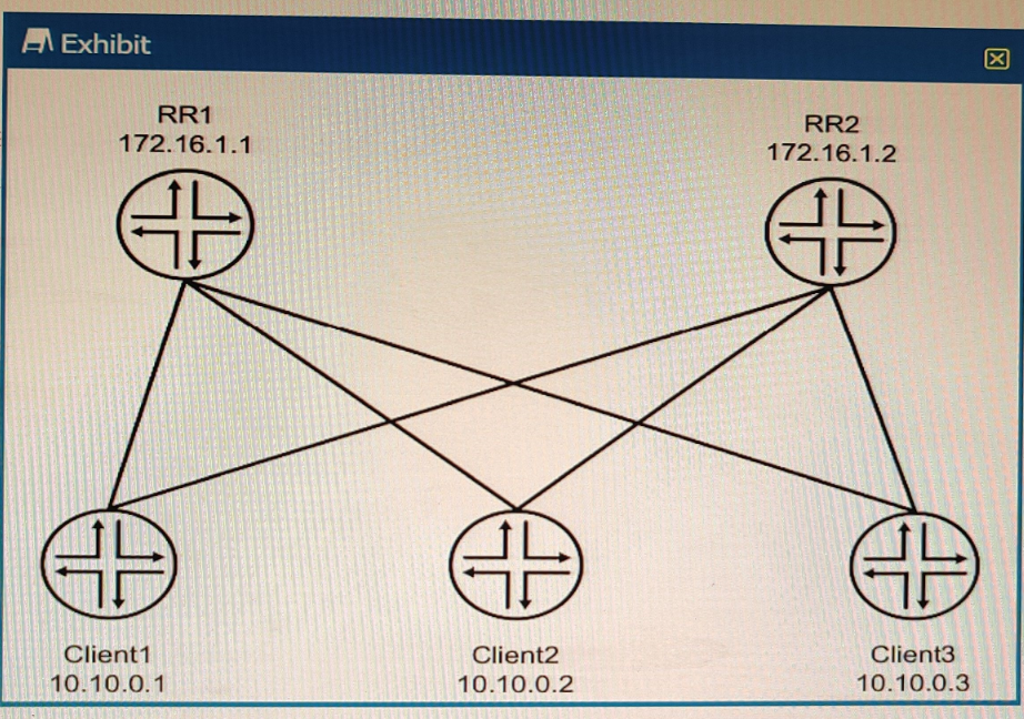
The environment is using BGP All devices are in the same AS with reachability redundancy Referring to the exhibit, which statement is correct?
BGP route reflectors are BGP routers that are allowed to ignore the IBGP loop avoidance rule and advertise IBGP learned routes to other IBGP peers under specific conditions. BGP route reflectors can reduce the number of IBGP sessions and updates in a network by eliminating the need for a full mesh of IBGP peers. BGP route reflectors can have three types of peerings:
EBGP neighbor: A BGP router that belongs to a different autonomous system (AS) than the route reflector.
IBGP client neighbor: An IBGP router that receives reflected routes from the route reflector. A client does not need to peer with other clients or non-clients.
IBGP non-client neighbor: An IBGP router that does not receive reflected routes from the route reflector. A non-client needs to peer with other non-clients and the route reflector.
In the exhibit, we can see that RR1 and RR2 are route reflectors in the same AS with reachability redundancy. They have two types of peerings: EBGP neighbors (R1 and R4) and IBGP client neighbors (Client1, Client2, and Client3). RR1 and RR2 are also peered with each other as IBGP non-client neighbors.