Key details for this exam, checked against the published exam outline
Each question shows the correct answer and an explanation of why it is right
[Exhibit]
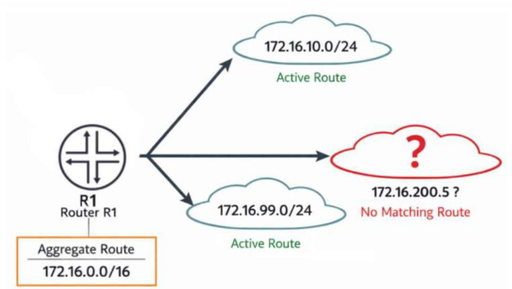
Click the Exhibit button.
You configure the aggregate route 172.16.0.0/16 on router R1. The routing table currently contains active routes for 172.16.10.0/24 and 172.16.99.0/24. No other more-specific routes exist.
Referring to the exhibit, which statement describes what R1 would do with traffic destined to 172.16.200.5?
The destination address 172.16.200.5 falls within the 172.16.0.0/16 aggregate's summarized range but does not fall within either of the two active, more-specific contributing routes actually present in the table --- 172.16.10.0/24 and 172.16.99.0/24 --- meaning no route more specific than the /16 itself exists to cover it. Under Junos's longest-match forwarding logic, the lookup for 172.16.200.5 therefore resolves to the aggregate route itself, and since aggregate routes are installed by default with a reject next hop rather than any real forwarding path, the router drops the packet and simultaneously generates an ICMP destination-unreachable message back to the originating source, explicitly signaling that no valid path exists for that specific destination even though a covering summary is being advertised. This reject behavior is precisely why aggregate routes are valuable for reducing the number of routes advertised upstream while still providing clear, immediate feedback for traffic aimed at address space within the summary that has no genuine underlying route, rather than silently black-holing it or misdirecting it toward an unrelated contributing route's next hop. The aggregate route itself remains active and installed throughout this process --- a gap in contributing coverage does not deactivate the aggregate, since the aggregate's activation depends only on at least one contributing route being active, which is satisfied here by both existing /24 blocks. There is also no default route present in this scenario to fall back upon. Reference topics: Junos Enterprise Routing -- Protocol Independent Routing, Aggregate Route Reject Behavior for Uncovered Address Space.
How does BGP prevent routing loops between internal peers?
BGP employs two distinct loop-prevention mechanisms depending on whether peers are external or internal to the same autonomous system. Between external peers (EBGP), loop prevention relies on the AS path attribute: every time a route crosses an AS boundary, the local AS number is prepended to the path, and a router rejects any incoming route whose AS path already contains its own AS number, since that would indicate the route has looped back around. Between internal peers (IBGP) within the same AS, however, the AS path attribute never changes, because IBGP does not add AS numbers as routes are readvertised internally --- meaning AS path alone cannot detect an internal loop. Instead, IBGP enforces a strict split-horizon-style rule: a router that learns a route via IBGP must never readvertise that route to another IBGP peer. This rule guarantees that every IBGP speaker within the AS must be directly peered with every other IBGP speaker (a logical full mesh) in order for all routers to receive all routes, since no IBGP router will relay IBGP-learned routes onward on another router's behalf. This full-mesh requirement is precisely why techniques such as route reflection and confederations were later developed --- they preserve the same loop-prevention guarantee while relaxing the physical full-mesh peering burden. VRRP and BFD serve entirely unrelated purposes (gateway redundancy and fast failure detection, respectively) and play no role in BGP loop prevention. Reference topics: Junos Enterprise Routing -- BGP, IBGP Split-Horizon and the Full-Mesh Requirement.
[Exhibit]
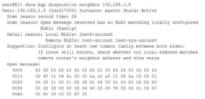
Click the Exhibit button.
You have two routers on your network that are not able to establish BGP sessions.
Which two statements are correct in this scenario? (Choose two.)
The diagnostic output explicitly states the root cause: the local router has only the inet6-unicast address family configured for this peer, while the remote router advertised inet-unicast and inet-vpn-unicast in its OPEN message, and BGP requires at least one common negotiated address family (NLRI type) between two peers for a session to remain established; with zero overlap between the two sides' configured families, the session is torn down immediately after the OPEN exchange, which is precisely why the peer state shows Active rather than Established. This confirms the mismatched-address-family statement directly and unambiguously from the exhibit's own Down reason and Detail reason fields. The diagnostic tool's own embedded Suggestion text goes further, explicitly advising the administrator to additionally verify that the local-address configured for the peer matches the remote router's configured neighbor address and vice versa --- a secondary, commonly encountered condition in which mismatched or effectively duplicated/incorrect address bindings between the two sides' neighbor statements can independently prevent a session from completing correctly, even once the family mismatch is resolved. This is why address-configuration consistency between the peers is flagged as a second concern worth checking in this scenario. Nothing in the exhibit references NTP or time synchronization at all, nor does anything in the output reference authentication, an MD5 mismatch, or any related failure signature; both of those conditions would present through entirely different diagnostic messages than the one shown here. Reference topics: Junos Enterprise Routing -- BGP, Address Family Negotiation and the show bgp diagnostics neighbor Command.
You need to block SSH (TCP port 22) traffic from the 192.168.10.0/24 network.
Which firewall filter term is correct in this scenario?
Correctly blocking SSH traffic originating from a specific network requires matching three precise conditions simultaneously in the from clause: the traffic's source-address must equal the 192.168.10.0/24 network, since the requirement is to block traffic coming from that network rather than traffic destined to it; the protocol must be explicitly set to tcp, since SSH operates exclusively over TCP; and the destination-port must be set to 22, because an inbound SSH connection request is always directed at the well-known SSH listening port 22 on the receiving side, regardless of which ephemeral source port the initiating client happens to use. The first option satisfies all three conditions correctly and pairs them with a discard action, cleanly dropping matching traffic. The second option incorrectly substitutes destination-address for source-address, which would match traffic heading toward that /24 rather than traffic originating from it, inverting the intended match direction. The third option incorrectly uses source-port 22 instead of destination-port 22; since the SSH client's source port is a randomly assigned ephemeral value rather than a fixed 22, this term would almost never match real SSH session-initiation traffic. The fourth option relies on a service ssh match condition, which is not valid syntax within the standard Junos firewall filter grammar for family inet; there is no such application-based keyword available at that hierarchy, making the term invalid regardless of the reject action chosen. Reference topics: Junos Enterprise Switching -- Firewall Filters, Matching on Address, Protocol, and Port Conditions.
You implement FBF on router R1 so that traffic from subnet 172.25.0.0/24 uses ISP-A and traffic from subnet 172.25.1.0/24 uses ISP-B. You create forwarding instances for ISP-A and ISP-B. You also configure static default routes inside each instance. However, the static default routes remain inactive.
In this scenario, which action would complete the FBF implementation?
A classic and well-documented gotcha in filter-based forwarding deployments is that the static default route configured inside each forwarding instance frequently references a next-hop address that Junos cannot resolve, simply because the interface and other directly connected routes needed to validate that next hop as reachable exist only in the master inet.0 table by default, not automatically inside the newly created forwarding instance's own table. Since a static route's next hop must be resolvable against routes present within its own routing table to become active, the static default routes inside the ISP-A and ISP-B forwarding instances remain inactive precisely because the necessary interface/next-hop routes were never made visible inside those instances. The standard solution taught for this exact FBF scenario is to configure a routing information base (RIB) group that explicitly imports the relevant interface routes between the master inet.0 table and each forwarding instance's table, allowing the static default route's next hop inside each instance to resolve correctly against the leaked routes and become active. Applying a firewall filter without ever attaching it to an interface accomplishes nothing, since an unapplied filter never evaluates any traffic. Increasing the static route's preference value only affects which competing route wins selection and does nothing to resolve an unreachable next hop. Changing the instance type away from forwarding (to virtual-router) would in fact break FBF entirely, since filter-based forwarding specifically depends on the forwarding instance type working together with a routing-instance firewall filter action. Reference topics: Junos Enterprise Routing -- Protocol Independent Routing, Filter-Based Forwarding and RIB Group Route Leaking.
Which two statements describe the purpose of a BGP notification message? (Choose two.)
A BGP NOTIFICATION message is one of the four core message types defined in RFC 4271, alongside OPEN, UPDATE, and KEEPALIVE, and it serves a very specific and narrow purpose within the protocol: whenever a BGP speaker detects an unrecoverable, fatal condition in the session --- such as a malformed OPEN message, an unsupported capability, a hold-timer expiration, a finite-state-machine error, or an administratively initiated reset --- it transmits a NOTIFICATION message to its peer immediately before closing the underlying TCP connection and tearing down the session entirely. This confirms that a NOTIFICATION always signals the termination of the session upon a fatal error, never a routine, in-session update. Structurally, every NOTIFICATION message carries a defined error code and error subcode field, which together precisely classify the category and specific nature of the fault that triggered the termination (for example, 'Cease' with a subcode indicating administrative shutdown, or 'Update Message Error' with a subcode indicating a malformed attribute), giving the receiving peer's administrator concrete diagnostic information about exactly why the session was torn down. Updating route attributes while keeping a session alive is the role of the UPDATE message, not NOTIFICATION, and refreshing a neighbor's table without resetting the session describes the optional Route Refresh capability (a separate, distinct BGP mechanism), neither of which describes NOTIFICATION's function. Reference topics: Junos Enterprise Routing -- BGP, BGP Message Types and the NOTIFICATION Message.
Which sequence correctly describes the basic message flow that leads to a successful BGP peering session?
RFC 4271 defines the BGP finite state machine as a strict, ordered progression of six states that a session must move through to successfully establish. A newly configured or reset session always begins in Idle, where BGP initializes resources and refuses connections until the ConnectRetry timer fires. From Idle, the router transitions to Connect and attempts to establish the underlying TCP transport session to the configured peer address on port 179. If that TCP attempt does not immediately succeed, the session falls back to the Active state, where the router continues retrying the TCP connection in the background; once the TCP handshake finally completes (from either Connect or Active), the session advances to OpenSent, during which the router transmits its own BGP OPEN message advertising its AS number, hold time, BGP identifier, and capabilities. Upon receiving and validating a compatible OPEN message from the peer, the session moves to OpenConfirm, where both sides exchange KEEPALIVE messages to confirm the parameters negotiated in the OPEN exchange are mutually acceptable. Only after this confirmation does the session reach Established, the final state in which UPDATE messages carrying actual routing information begin to flow between the peers. Any deviation from this Idle Connect Active OpenSent OpenConfirm Established ordering, as presented in the other answer choices, does not reflect the standardized BGP state machine. Reference topics: Junos Enterprise Routing -- BGP, The BGP Finite State Machine.
Exam domains verified against: Official Juniper JN0-352 exam guide, last checked October 2026.
Learn bridging components, frame processing, VLAN ports, tagging, native and voice VLANs, and inter-VLAN routing configuration on Junos platforms. These concepts underpin your ability to segment networks and manage traffic within enterprise switching environments.
Sample question from this domain above: Q1
Understand STP and RSTP concepts including port roles, states, BPDUs, and convergence behaviour. Configure and troubleshoot spanning tree to prevent loops and ensure redundant switch connections work properly in enterprise networks.
Master BPDU protection, loop protection, root protection, port security with MAC limiting, DHCP snooping, Dynamic ARP Inspection, IP source guard, MACsec and storm control. Apply firewall filters at Layer 2 to protect switch infrastructure from common attacks.
Sample question from this domain above: Q3
Work with static routes, aggregate routes, generated routes, martian addresses, routing instances and RIB groups. Configure load balancing and filter-based forwarding to distribute traffic and implement policy-based routing without relying on dynamic protocols.
Sample question from this domain above: Q2
Learn OSPF operation, link-state databases, packet types, router IDs, adjacencies, designated and backup designated routers, area types and LSAs. Configure areas and interfaces, apply routing policies, and use troubleshooting tools to verify OSPF behaviour in enterprise networks.
Sample question from this domain above: Q6
Understand IS-IS PDUs, TLVs, adjacencies, levels, designated intermediate systems and metrics. Configure IS-IS levels and interfaces, manage adjacencies, apply routing policies and apply troubleshooting techniques to diagnose IS-IS problems in multi-level networks.
Master BGP operation, message types, attributes and route selection logic. Work with internal and external BGP peers, configure groups and neighbors, apply routing policies to control advertisements and manipulate path selection in large interconnected networks.
Learn IP tunneling concepts with GRE and IP-IP encapsulation. Configure tunnels for site-to-site connectivity, understand tunnel applications and requirements, and use standard troubleshooting tools to verify tunnel operation and diagnose connectivity issues.
Sample question from this domain above: Q7
Understand LAGs, redundant trunk groups, virtual chassis, graceful restart, GRES, NSR, NSB, BFD, VRRP and ISSU. Configure redundancy mechanisms to eliminate single points of failure and enable non-disruptive software upgrades in mission-critical enterprise networks.
Common questions about the exam itself

