Key details for this exam, checked against the published exam outline
Each question shows the correct answer and an explanation of why it is right
You are creating an IP fabric underlay and want to use OSPF as your routing protocol.
In this scenario, which statement is correct?
When creating an IP fabric underlay using OSPF as the routing protocol, consistent interface speeds are important to ensure optimal traffic distribution and utilization of all links.
Step-by-Step Breakdown:
OSPF and Interface Speeds:
OSPF calculates the cost of a link based on its bandwidth. The default cost calculation in OSPF is:
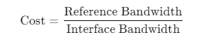
If interface speeds vary significantly, OSPF may choose paths with lower cost (higher bandwidth), resulting in some links being underutilized.
Equal Utilization:
To ensure that all links are equally utilized in an IP fabric, it is recommended to maintain uniform interface speeds across the fabric. This ensures balanced load sharing across all available paths.
Juniper Reference:
IP Fabric with OSPF: Juniper recommends consistent interface speeds to maintain even traffic distribution and optimal link utilization in IP fabric underlay designs.
Referring to the exhibit,
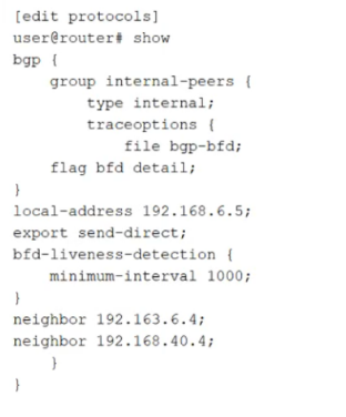
how much time must pass before a neighbor is considered down?
The exhibit shows BFD liveness detection configured under a BGP group with minimum-interval set to 1000 milliseconds. In Junos, BFD provides rapid failure detection by sending periodic BFD control packets between neighbors. The minimum-interval value is the negotiated minimum transmit and receive interval used for BFD control packets for that session. A neighbor is declared down when the local system fails to receive a certain number of consecutive BFD packets within the expected time window.
That time window is determined by the BFD detection time, which is calculated as the minimum-interval multiplied by the BFD multiplier. The multiplier represents how many BFD control packets can be missed before the session is considered failed. If the multiplier is not explicitly configured, Junos uses the default multiplier value of 3. Therefore, with minimum-interval set to 1000 ms and the default multiplier of 3, the detection time becomes 3000 ms. After approximately 3 seconds without receiving the expected BFD control packets, the BFD session transitions to down and BGP can react by treating the associated peer as unreachable for fast convergence.
This behavior is commonly used in data center underlays and EVPN fabrics to reduce convergence time compared to relying only on BGP hold timers.
Which statement is correct about building an IP fabric?
A modern IP fabric in a leaf spine topology is built to deliver predictable latency, high bandwidth, and horizontal scale. The defining characteristic is that every leaf switch connects upstream to every spine switch. This full mesh between leaf and spine layers creates multiple equal cost paths between any two endpoints connected anywhere in the fabric. With this design, east west traffic between servers attached to different leaves can traverse the fabric using one spine hop, keeping path length consistent and enabling efficient load sharing across links.
Leaf to leaf direct connections are not used in a standard leaf spine IP fabric because they create irregular topologies, complicate troubleshooting, and undermine the uniform multi path behavior that makes fabrics scalable. Similarly, a leaf does not inherently require two or more physical connections to each spine. Many designs start with a single link per leaf spine pair and increase capacity by adding additional parallel links as needed. Redundancy is achieved by having multiple spines and multiple equal cost paths, not by mandating multiple links to every spine from day one.
Server connectivity requirements also vary. Some servers use single uplinks, others use dual homing for redundancy. That decision is independent of the fundamental requirement that each leaf should connect to every spine.
Refer to the exhibit.
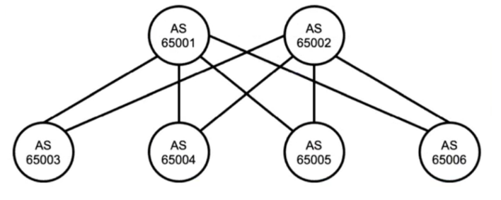
Referring to the exhibit, which two statements are true about BGP? Choose two.
The diagram shows multiple autonomous systems, with each device labeled with a different AS number. Because the peers are in different autonomous systems, the correct BGP session type is external BGP. In a typical Juniper data center IP fabric underlay, this design is intentional: EBGP is used between leaf and spine devices to simplify policy boundaries, improve operational clarity, and avoid the additional mechanisms commonly required in large internal BGP designs.
In an EBGP-based underlay, neighbors are most commonly formed over the directly connected point-to-point links between leaf and spine. That means the BGP peering is established using the IP addresses configured on those physical routed interfaces, not loopback addresses. Using physically connected addresses aligns with the default EBGP behavior where the TTL is one hop, and it reduces configuration complexity because no multihop settings or additional reachability dependencies are required to bring up the session.
Peering using loopbacks is possible, but it typically requires EBGP multihop and a routing method to ensure reachability to the remote loopback before BGP can establish. That approach is more common for overlay control-plane sessions or for specific design requirements, rather than for the simplest and most common underlay implementation. Therefore, the two true statements are that the exhibit uses EBGP and that devices should peer using physically connected IP addresses.
Referring to the exhibit, which type of protocol session will be established?
The configuration shown is under protocols bgp and defines a BGP group named service-pod with the statement type internal. In Junos, the BGP group type determines whether the sessions formed by neighbors in that group are treated as internal BGP or external BGP. When the group is set to type internal, the router establishes an iBGP session to the configured neighbor address. That means both peers are expected to be in the same autonomous system, and the session is used to exchange routes within that single AS.
The local-address statement sets the source address that the router will use when initiating the TCP connection for BGP. In data center designs, this is commonly a loopback address so the session can be resilient and independent of any single physical interface. The neighbor statement identifies the remote peer address. With type internal, the session is iBGP even if the neighbor is directly connected, because the relationship is defined by AS scope rather than topology.
OSPF and IS-IS are different routing protocols entirely and are not established through BGP configuration. EBGP would require type external and typically involves different AS numbers across the peering. Therefore, the only correct answer is IBGP.
You have a problem bringing up an aggregated Ethernet interface between a spine and a leaf.
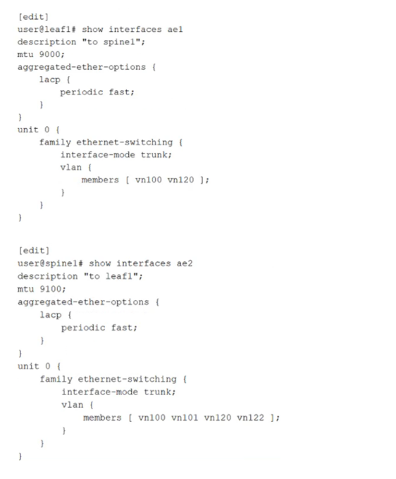
Referring to the exhibit, what is the problem?
An aggregated Ethernet interface that uses LACP requires at least one side to actively initiate LACP negotiations. In the exhibit, both devices have LACP configured only with periodic fast, but neither side explicitly enables LACP active mode. When both ends operate in passive behavior, each side waits for the other to send LACP Data Units, and no negotiation begins. As a result, the LACP state does not progress to collecting and distributing, and the aggregated link fails to form as expected. Adding the active statement under the LACP hierarchy on one or both ends ensures that LACP frames are transmitted and the bundle can be negotiated and brought up.
The other options are not the root cause for bringing the bundle up. The aggregated Ethernet interface number does not need to match across devices because the bundle is locally significant on each system. VLAN membership differences on a trunk do not prevent LACP from establishing the aggregate; they only affect which tagged VLANs are allowed to pass once the link is operational. MTU differences can cause data plane issues such as fragmentation or drops for jumbo frames, but they do not typically prevent LACP formation because control frames are small and the physical link can still come up.
Exam domains verified against: Official Juniper JN0-281 exam guide, last checked October 2026.
Identify traditional multitier and IP fabric spine-leaf architectures. Understand Layer 2 and Layer 3 strategies, overlay versus underlay networks, and EVPN-VXLAN basics and purpose in data center design.
Sample question from this domain above: Q3
Identify Ethernet switching and bridging concepts for Junos OS. Understand VLAN port modes, tagging, and Integrated Routing and Bridging (IRB) functionality and benefits.
Identify traditional multitier and IP fabric spine-leaf architectures. Understand Layer 2 and Layer 3 strategies, overlay versus underlay networks, and EVPN-VXLAN basics and purpose in data center design.
Identify static, aggregate, and generated routes, Martian addresses, and routing instances with RIB groups. Configure, monitor and troubleshoot load balancing and filter-based forwarding.
Identify OSPF link-state databases, packet types, Router ID, adjacencies, designated routers, areas and LSA types. Identify and configure BGP operation, message types, attributes, path selection, and IBGP-EBGP interaction.
Identify Link Aggregation Groups, Graceful Restart, Bidirectional Forwarding Detection, and Virtual Chassis concepts and benefits. Configure, monitor and troubleshoot these high-availability components.
Common questions about the exam itself

