Key details for this exam, checked against the published exam outline
Each question shows the correct answer and an explanation of why it is right
A pair of CX 8325 series switches a configured in a VSX cluster. Which function is executed on both VSX members during normal operation?
The question asks which function is executed on both VSX members (CX 8325 switches) during normal operation in a VSX cluster.
Analysis of Options:
Option A: Correct. Both VSX switches reply to ARP requests with the cluster's virtual MAC (vMAC) for SVIs configured with active-gateway, ensuring consistent Layer 3 forwarding.
Option B: Incorrect. PIM (Protocol Independent Multicast) and PIM-DR roles are typically handled by one switch, not both, in a VSX cluster.
Option C: Incorrect. DHCP relay or server functions are not necessarily performed by both switches simultaneously.
Option D: Incorrect. Gratuitous ARP and broadcast hello packets are typically sent by the primary switch or specific protocols, not both VSX members for all cases.
Why Option A is Correct: In a VSX cluster, the active-gateway feature allows both switches to respond to ARP requests for Switched Virtual Interfaces (SVIs) using a shared virtual MAC address (vMAC). This ensures seamless Layer 3 forwarding and high availability, as clients receive consistent ARP replies regardless of which VSX switch processes the request. The vsx-sync feature ensures the vMAC is synchronized, enabling both switches to perform this function during normal operation, as per HPE Aruba Networking's VSX architecture.
Relevance to Certification Objectives:
Network Resiliency and Virtualization (8%): Designing and troubleshooting VSX for redundancy and active-active forwarding.
Switching (19%): Implementing Layer 2/3 technologies, including ARP handling in VSX.
Routing (16%): Ensuring consistent Layer 3 operations in VSX environments.
HPE Aruba Networking AOS-CX Configuration Guide: VSX Configuration, detailing active-gateway and vMAC usage.
HPE7-A06 Study Guide: Covers VSX Layer 3 functions and ARP handling.
HPE Aruba Networking Technical Documentation: VSX Active-Gateway Best Practices.
Refer to the exhibit.
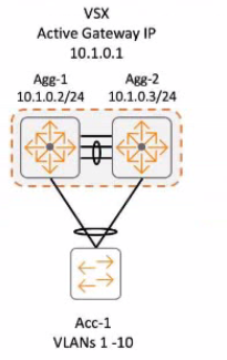
IGMP v3 was enabled on both VSX switches. Which switch becomes the IGMP querier for clients connected to Ace-1 switch?
The setup has Agg-1 and Agg-2 as a VSX pair with IGMPv3 enabled. Ace-1 is a downstream switch connected to clients. The question asks which switch becomes the IGMP querier for clients connected to Ace-1.
IGMP Snooping & Querier: In a Layer 2 network using IGMP snooping, an IGMP querier is required on each VLAN to periodically send general queries. This prompts hosts to send membership reports, allowing snooping switches to learn which ports need which multicast streams.
Querier Election: If multiple devices capable of querying exist on a VLAN (like routers or capable switches), an election occurs. Typically, the device with the lowest IP address on the VLAN becomes the querier.
VSX & IGMP Querier: In an ArubaOS-CX VSX environment, the IGMP querier functionality is managed by the VSX pair. Documentation indicates that the primary VSX switch typically assumes the role of the IGMP querier for the VLANs it serves, including those extended via MC-LAG to downstream switches.
Analysis of Options:
A . Agg-2: Would only be the querier if it were the primary VSX switch.
B . Both Agg-1 and Agg-2: Incorrect, only one active querier per VLAN is standard.
C . Agg-1: Likely the primary VSX switch (often designated or wins election based on priority/lower system MAC/IP) and thus becomes the querier.
D . Active gateway IP: This is the virtual IP used for unicast routing, but the querier function runs on a physical switch, usually the primary.
Conclusion: Assuming Agg-1 is the primary VSX switch (as is common convention or based on default election parameters if not explicitly configured), it will act as the IGMP querier for the VLAN serving clients connected to Ace-1.
Exhibit.
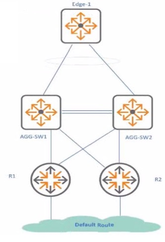
In the given example AGG-SW1 and AGG-SW2 use CX 8325 in VSX and Edge-1 with CX 6200F. You want to avcwl sub-optimal path.ng and ISL traffic for the VSX and upstream routers R1 and R2.
What is the HPE Aruba Networking recommended solution for me SVIs on the VSX switches connected to R1 and R2?
The scenario involves a VSX pair (AGG-SW1/SW2) connected upstream to routers R1/R2. The goal is to configure the SVIs on the VSX switches facing these upstream routers optimally to avoid suboptimal L3 paths and unnecessary traffic over the VSX Inter-Switch Link (ISL).
VSX L3 Interface Options:
Active Gateway: Primarily designed for downstream SVIs to provide a redundant default gateway to clients/access switches. Not typically used for upstream routed interfaces.
Active Forwarding: Specifically designed for upstream routed interfaces (physical or SVIs) on a VSX pair. It allows both VSX members to actively route traffic arriving on that interface locally, without needing to forward L3 traffic across the ISL. This ensures optimal routing and utilizes both members effectively.
Unicast IP (Standard IP): Without specific VSX features, standard routing applies. This could lead to suboptimal paths if, for example, return traffic prefers one VSX switch, but the optimal path requires crossing the ISL.
VRRP: Can be run between VSX members but adds complexity and is generally superseded by Active Gateway (downstream) or Active Forwarding (upstream) in VSX designs.
Analysis of Options:
A . Configure active-forwarding: This enables local L3 forwarding on both VSX members for the upstream SVI, preventing unnecessary ISL traversal for routed traffic. This is the recommended best practice.
B . Configure unicast IP: Standard configuration, potentially leading to suboptimal paths/ISL usage.
C . Configure VRRP virtual-ip: Not the recommended approach for upstream links in VSX.
D . Configure active-gateway: Incorrect, Active Gateway is for downstream SVIs.
Conclusion: Using active-forwarding on the SVIs facing the upstream routers (R1/R2) is the HPE Aruba Networking recommended solution to ensure optimal routing and minimize L3 traffic across the ISL.
Refer to the exhibit.
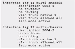
A gateway cluster needs to be connected to the VSX-enabled switches where MC-LAG is configured What Is a possible constraint?
The question asks about a possible constraint when connecting an Aruba Gateway Cluster to upstream VSX switches using an MC-LAG.
Scenario: Gateway Cluster acts as a single logical device forming an LACP LAG. The VSX switches are configured with MC-LAG, allowing the gateway cluster to bundle links across the two physical VSX switches.
LACP & Initial Provisioning: LACP requires negotiation (exchange of LACP PDUs) between both ends of the link bundle to activate the LAG. During initial gateway provisioning (ZTP, OTP), the gateway might be in a minimal state without its full configuration, including LACP parameters. If the VSX switch ports are configured strictly for LACP active mode, the LAG might not form until the gateway is fully provisioned and running LACP. This lack of connectivity during provisioning is a constraint.
Analysis of Options:
A: lacp mode active is standard, but the issue is during provisioning, not runtime mode choice. 'static-activate' is unrelated.
B: The absence of lacp fallback could be the constraint. Fallback allows connectivity if LACP doesn't establish, which is useful during provisioning.
C: LLDP is not required for LACP.
D: Correctly identifies the constraint: Standard LACP required by the switch might not be supported or active on the gateway during its initial provisioning phase, potentially hindering the setup process. Workarounds like disabling LACP or enabling LACP fallback on the switch ports during this phase are often necessary.
Conclusion: LACP incompatibility during the initial provisioning phase of the gateway cluster is a common constraint when connecting to switches requiring LACP for the LAG.
A plying the command "ip Igmp snooping blocked VLAN 6. 6* on a port ...
The question asks for the effect of applying the command ip igmp snooping blocked vlan 5,6 on a switch port.
ip igmp snooping blocked vlan <vlan-list>: This interface configuration command instructs the IGMP snooping process on the switch to block (ignore/drop) any inbound IGMP control packets (specifically Membership Reports, i.e., 'joins', and Leave messages) received on this port for the specified VLANs (5 and 6 in this case).
Effect: By blocking IGMP join messages from hosts connected to this port, the switch will not learn about any multicast group memberships requested by those hosts in VLANs 5 and 6. Consequently, the switch will not forward multicast traffic for those groups out of this port for those VLANs (unless the port is designated as a multicast router port). It effectively prevents hosts on this port from receiving multicast streams in the specified VLANs via standard IGMP mechanisms.
Analysis of Options:
A: It results in traffic effectively being pruned because memberships aren't learned, but the command itself blocks the IGMP control packets (joins).
B: Correct. It stops the switch from accepting IGMP join messages on this port for VLANs 5 and 6.
C: Incorrect. It doesn't control inter-VLAN traffic.
D: Incorrect. It doesn't disable the entire port.
Conclusion: The command specifically blocks the reception and processing of IGMP join messages on the configured port for the listed VLANs.
You have recently configured a switch for 802.IX authentication with HPE Aruba Networking ClearPass. A security admin is seeing events with the following description in ClearPass Event Viewer.
RADIUS authentication attempt from unknown NAD (10.10.1.10:1812)'
Which command should you us to identify the configuration issue?
The ClearPass Event Viewer message 'RADIUS authentication attempt from unknown NAD (10.10.1.10:1812)' indicates that ClearPass received a RADIUS request from the IP address 10.10.1.10, but this IP is not configured as a trusted Network Access Device (NAD) in ClearPass's network device list, or the shared secret doesn't match. The first step in troubleshooting on the switch side is to verify which source IP address the switch is actually using to send these RADIUS requests.
RADIUS Source IP: AOS-CX switches can be configured to use a specific source IP address for RADIUS packets, often using the ip source-interface radius [vrf <vrf-name>] command. This is important if the switch has multiple IP interfaces or uses VRFs.
Analysis of Commands:
A . show ip source-interface radius: This command directly displays the configured source interface and IP address used for RADIUS communications, allowing comparison with the IP configured in ClearPass.
B . show aaa authentication-server radius: Shows server group configuration, not the source IP used by the switch.
C . show radius-server shared-secret: Not a standard command; secrets are usually masked in other commands.
D . show radius-server detail: Shows configured RADIUS server details but doesn't explicitly show the source IP the switch is using to originate packets.
Conclusion: To identify why ClearPass sees requests from an 'unknown NAD' IP (10.10.1.10), the first step on the switch is to confirm which source IP it's using. show ip source-interface radius provides this crucial information.
Refer to the exhibit which illustrates the current configuration of Router-1.

Clients of VLAN 10 require access to services hosted in the 10.1.100.0/24 subnet. This 'equites one 01 more routes to be added to Rculer-1 that do not currently exist.
Which script would install a route from 10.2.10.0/24 to 10.1.100.0/24 on Router-1? A return path is not required as part of this answer.
The goal is to add a static route on Router-1 to allow clients in VLAN 10 (subnet 10.2.10.0/24, presumably in VRF 'IoT-Medical' based on options) to reach services in the 10.1.100.0/24 subnet. The exhibit indicates interface 1/1/1 (IP 10.255.101.10/24) is in VRF 'service', and the likely next hop towards the destination is Core-1 at 10.255.101.11 (also implied to be reachable via VRF 'service'). This requires adding a route in the source VRF ('IoT-Medical') pointing towards the destination via the next hop in the 'service' VRF.
Static Route Syntax (with VRF): ip route <destination_prefix> <next-hop-ip> [vrf <source-vrf>]
Analysis of Options:
A: Claims Core-1 isn't in VRF 'service', contradicting the likely setup.
B: Uses unusual interface:ip syntax (1/1/1:10.255.101.11). Defines the route in VRF 'IoT-Medical'.
C: Uses interface 1/1/1 as the next hop. This is less specific than using the IP address and relies on the interface being point-to-point or having proxy ARP enabled. Defines the route in VRF 'IoT-Medical'.
D: ip route 10.1.100.0/24 10.255.101.11 vrf IoT-Medical. This uses the standard syntax to define a static route for the destination 10.1.100.0/24 via the next-hop IP 10.255.101.11 within the context of the IoT-Medical VRF. The successful function of this route depends on inter-VRF routing (route leaking) being configured between 'IoT-Medical' and 'service' VRFs, but the command itself correctly defines the desired static route.
Conclusion: Option D provides the correct and standard command syntax to configure the required static route within the specified source VRF ('IoT-Medical').
Exam domains verified against: Official HP HPE7-A06 exam guide, last checked October 2026.
Analyze customer network issues and troubleshoot problems. Understand how components of a network stack interact and identify failures quickly.
Develop configurations based on customer requirements and apply advanced networking architectures. Identify design problems and troubleshoot device deployment scenarios.
Design and troubleshoot mechanisms for resiliency, redundancy, and fault tolerance. Implement solutions that maintain service continuity in campus networks.
Sample question from this domain above: Q6
Implement, troubleshoot, and remediate Layer 2 and 3 switching including broadcast domains and interconnection technologies. Work with VLAN tagging and switch port configurations.
Design and troubleshoot RF attributes and wireless functions for campus networks. Build configurations based on customer requirements and implement Layer 2 interconnection.
Design and troubleshoot routing topologies and functions across campus networks. Understand how routing decisions affect network performance and convergence.
Design and troubleshoot security implementation in customer networks. Work with wired 802.1X, EAP-TLS authentication, and Group Based Policy configurations.
Design and troubleshoot AAA configurations based on customer requirements. Create and analyze ClearPass integration with campus access infrastructure.
Sample question from this domain above: Q3
Perform advanced troubleshooting and remediation of campus network problems. Use diagnostic tools and methodologies to resolve complex issues.
Analyze and remediate performance issues in campus networks. Identify bottlenecks and optimize configurations for throughput and latency.
Sample question from this domain above: Q5
Common questions about the exam itself

