The Cisco Certified Network Associate Exam (200-301) validates your ability to install, configure, and troubleshoot small to medium-sized enterprise networks. This certification demonstrates competency across networking fundamentals, security, and modern automation practices, skills essential for network engineers and IT professionals. This page provides a clear roadmap of exam topics, question formats, and actionable study strategies to help you prepare efficiently and confidently for the Cisco Certified Network Associate path.
Use this topic map to guide your study for Cisco 200-301 (Cisco Certified Network Associate Exam) within the Cisco Certified Network Associate path.
The 200-301 exam uses multiple question types to assess both theoretical knowledge and practical decision-making. Each format is designed to measure how well you can apply networking concepts in real-world scenarios.
Questions progress in difficulty, starting with foundational knowledge and advancing to complex scenarios that mirror challenges you will encounter in production networks.
An effective study plan distributes your effort across all six domains while allowing time for hands-on practice and review. Allocate roughly 4-6 weeks to cover the material thoroughly, with increasing focus on weak areas as your exam date approaches.
Explore other Cisco certifications: view all Cisco exams.
Strengthen your preparation with up-to-date resources from validexamdumps.com. These materials align to 200-301 and cover practical scenarios with clear explanations.
Visit the exam page to download the PDF, Online Practice Test, or get a Bundle Discount offer for both formats: Cisco Certified Network Associate Exam.
Network Fundamentals and IP Connectivity typically account for a larger portion of the exam, as they form the foundation for all other domains. However, all six topics are tested, so balanced preparation across all areas is essential. Review the official Cisco exam blueprint to see the exact percentage breakdown for each domain.
In practice, these domains overlap continuously. For example, you configure Network Access (VLANs and switching) to segment traffic, then use IP Connectivity (routing) to move data between segments, secure it with Security Fundamentals (access lists), and automate management with Automation and Programmability scripts. Understanding these connections helps you see the bigger picture and answer scenario-based questions more effectively.
Hands-on experience is highly valuable for retention and confidence. Aim to practice configuring routers and switches, setting up OSPF and EIGRP, deploying DHCP and NAT, and implementing access control lists in a lab environment. Even 20-30 hours of focused lab work on core tasks will significantly improve your ability to answer simulation-style questions and troubleshoot real scenarios.
Candidates often rush through multiple-choice questions without reading all options carefully, confuse similar protocols (OSPF vs. EIGRP), or misunderstand the scope of a scenario-based question. Another frequent error is neglecting hands-on practice and relying only on reading materials. Finally, poor time management during the exam can leave difficult questions unanswered. Avoid these by practicing under timed conditions and reviewing explanations for every wrong answer.
In the final week, avoid learning new material; instead, take a full-length practice test, review your weak areas, and refresh your memory on command syntax and protocol behaviors. Practice pacing so you can complete all questions within the time limit. Get adequate sleep and manage stress through light review rather than cramming, which leads to confusion and reduced retention.
What are two reasons to implement DHCP in a network? (Choose two.)
Answer D,E is correct: D. dynamic control over the best path to reach an IP addressss; E. access a website by name instead of by IP addressss. Cisco wireless design separates RF behavior, client authentication, encryption, AP operating mode, and controller management. A WLC centralizes WLAN configuration and AP control, while lightweight APs use CAPWAP to register and exchange control/data information with the controller. Security choices such as WPA2/AES and WPA3/SAE are not interchangeable with older mechanisms such as WEP, TKIP, or RC4. RF questions also depend on channel planning: adjacent cells should avoid overlapping channels, and 5-GHz preference features reduce congestion in the 2.4-GHz band. The incorrect options generally confuse AP mode, authentication, encryption, or controller responsibilities. Cisco CCNA 200-301 v1.1 includes these items because wireless failures often come from using the right-looking feature in the wrong part of the WLAN design. The selected answer is the Cisco-consistent configuration or behavior for this wireless scenario.
An engineer is configuring a switch port that is connected to a VoIP handset. Which command must the engineer configure to enable port security with a manually assigned MAC address of abcd.abcd.abcd on voice VLAN 4?
switchport port-security mac-address abcd.abcd.abcd vlan voice. Cisco port security can bind a secure MAC address specifically to the access VLAN or to the voice VLAN. Because the handset is using voice VLAN 4, the manually assigned secure MAC must be applied with the vlan voice keyword. Adding only the MAC address does not identify the voice VLAN context. Using a numeric VLAN value in this syntax is not the correct way to identify the voice VLAN for port-security binding. Sticky learning is also wrong because the question asks for a manually assigned MAC address. Cisco CCNA 200-301 v1.1 Network Access expects engineers to distinguish data VLAN and voice VLAN behavior on the same switch port. The corrected command is switchport port-security mac-address abcd.abcd.abcd vlan voice.
Refer to the exhibit.
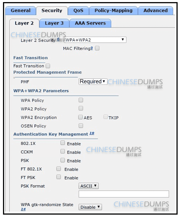
The network engineer is configuring a new WLAN and is told to use a preshared key for authentication instead of the RADIUS servers. Which additional set of tasks must the engineer perform to complete the configuration?
Select WPA2 Policy Disable PMF Enable PSK. Wireless questions depend on AP mode, WLAN security, RF band selection, controller interfaces, and client roaming or authentication behavior. Cisco CCNA 200-301 v1.1 includes this under Network Access, where the expected skill is selecting the feature that actually produces the requested network behavior. The wording normally gives the clue: protocol family, address scope, trunk state, route preference, security mode, API method, or controller role. Wrong options confuse encryption with authentication, local switching with tunneling, or controller management with client data handling. In production, choosing the wrong option would typically cause failed client access, a broken route, insecure management, or an automation workflow that targets the wrong interface. The selected answer is the Cisco-consistent behavior for this item.
Refer to the exhibit.
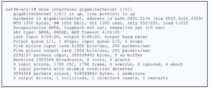
The switch cat9k acc.1 connects users to the campus LAN. Printing services are inaccessible through the network. Which interface issue is causing the connectivity problems?
A bad checksum is causing Ethernet frames to drop.. Cisco wireless design separates RF behavior, client authentication, encryption, AP operating mode, and controller management. A WLC centralizes WLAN configuration and AP control, while lightweight APs use CAPWAP to register and exchange control/data information with the controller. Security choices such as WPA2/AES and WPA3/SAE are not interchangeable with older mechanisms such as WEP, TKIP, or RC4. RF questions also depend on channel planning: adjacent cells should avoid overlapping channels, and 5-GHz preference features reduce congestion in the 2.4-GHz band. The incorrect options generally confuse AP mode, authentication, encryption, or controller responsibilities. Cisco CCNA 200-301 v1.1 includes these items because wireless failures often come from using the right-looking feature in the wrong part of the WLAN design. The selected answer is the Cisco-consistent configuration or behavior for this wireless scenario.
Refer to the exhibit.
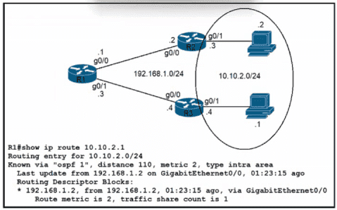
Refer to the exhibit. Traffic from R1 to the 10.10.2.0/24 subnet uses 192.168.1.2 as its next hop. A network engineer wants to update the R1 configuration so that traffic with destination 10.10.2.1 passes through router R3, and all other traffic to the 10.10.2.0/24 subnet passes through R2.
Which command must be used?
ip route 10.10.2.1 255.255.255.255 192.168.1.4 115. Cisco routing logic is deterministic: a router first matches the most specific destination prefix, then uses administrative distance when competing route sources advertise the same prefix, and finally evaluates the protocol metric when multiple paths remain inside the same routing protocol. First-hop redundancy protocols add a separate default-gateway resiliency function for hosts on a LAN. The other choices in this question either point to the wrong route-selection rule, confuse a protocol metric with administrative distance, or apply a Layer 2 concept where a Layer 3 forwarding decision is required. In production, that mistake would create blackholing, asymmetric routing, or a backup path that never activates. Cisco CCNA 200-301 v1.1 tests this because route selection is fundamental to troubleshooting reachability. The selected answer matches the behavior Cisco routers use when forwarding traffic or maintaining gateway redundancy.