The Autodesk Certified Professional in Revit for Electrical Design (RVT_ELEC_01101) validates your ability to design, analyze, and document electrical systems in Revit within the Autodesk AEC Certifications framework. This exam is designed for electrical professionals and BIM coordinators who work on building projects and need to demonstrate competency in Revit's electrical tools and workflows. This landing page provides a clear study roadmap, topic breakdown, and preparation strategies to help you pass with confidence. Whether you're new to Revit electrical design or refining your skills, understanding the exam structure and core domains is essential for effective preparation.
Use this topic map to guide your study for AutoDesk RVT_ELEC_01101 (Autodesk Certified Professional in Revit for Electrical Design) within the Autodesk AEC Certifications path.
The RVT_ELEC_01101 exam measures both conceptual knowledge and applied problem-solving through a mix of question types that reflect real-world electrical design scenarios.
Questions increase in complexity as you progress, moving from foundational concepts to integrated workflows that combine Analysis, Modeling, Documentation, Families, and Collaboration.
Effective preparation requires a structured study plan that maps the five core topics to manageable weekly goals and reinforces connections between concepts. Allocate time proportionally: spend more hours on Modeling and Documentation (typically weighted higher), but do not neglect Analysis and Families, which underpin sound design decisions.
Explore other AutoDesk certifications: view all AutoDesk exams.
Strengthen your preparation with up-to-date resources from validexamdumps.com. These materials align to RVT_ELEC_01101 and cover practical scenarios with clear explanations.
Visit the exam page to download the PDF, Online Practice Test, or get a Bundle Discount offer for both formats: Autodesk Certified Professional in Revit for Electrical Design.
Modeling and Documentation typically account for the largest portion of exam questions, reflecting their importance in real-world electrical design projects. However, all five domains (Analysis, Modeling, Documentation, Families, Collaboration) are tested, so balanced preparation is essential. Prioritize Modeling and Documentation in your final review, but do not skip the others.
Analysis informs the design (e.g., load calculations guide circuit sizing). Modeling translates that design into Revit geometry and components. Families provide the reusable building blocks for modeling. Documentation extracts schedules and drawings from the model. Collaboration ensures electrical work coordinates with architecture and MEP disciplines. Understanding these links helps you answer scenario-based questions more confidently.
Ideally, you should have completed at least one full electrical design project or equivalent lab work in Revit. If you are new to Revit electrical, prioritize hands-on tutorials covering circuit creation, device placement, panel schedules, and family editing. Practice questions and simulations can supplement limited field experience, but direct Revit experience accelerates learning and builds confidence.
Candidates often confuse shared families with project families, misunderstand how to resolve coordination warnings, or overlook code-compliance details in documentation questions. Another frequent error is rushing through scenario items without fully reading the project constraints. Slow down on complex questions, re-read the scenario, and double-check your answer logic before moving on.
In your final week, focus on high-confidence review rather than learning new material. Re-work practice questions you missed, paying close attention to explanations. Do one full-length timed mock test to simulate exam conditions and identify any remaining pacing issues. Spend your last two days reviewing Modeling and Documentation topics, and get adequate sleep the night before the exam.
Refer to the exhibit.
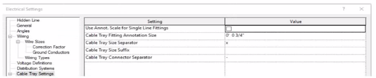
An electrical designer models a cable tray in a project and decides to check the box (or Use Annot. Scale tor Single Line Fittings and change the Cable Tray Fitting Annotation Size to 1/8" (3 mm).
What is the result?
(The image is presented m Imperial units: 1 In = 25 mm (Metric units rounded].)
In Autodesk Revit MEP, the Electrical Settings dialog box contains project-wide configuration parameters that affect all electrical systems, including Cable Tray Settings. This dialog allows users to control annotation scales, fitting symbols, and text size for documentation purposes.
The option labeled ''Use Annot. Scale for Single Line Fittings'' determines whether the cable tray fittings' annotation graphics automatically scale according to the view's annotation scale. When this box is checked, the annotation symbol size for fittings adjusts proportionally to the scale of the view.
Similarly, ''Cable Tray Fitting Annotation Size'' defines the annotation size for cable tray fittings in single-line representations (schematic views or simplified plan representations). Changing this parameter (for instance, from '' to '') modifies the visual representation globally for all cable tray fittings in the project, since the Electrical Settings dialog is a project-wide configuration, not a per-instance or per-view override.
According to the Autodesk Revit MEP User's Guide (Electrical Systems -- Cable Trays):
''Electrical settings define how cable trays and conduit are displayed throughout the project. Any change made to these settings, such as annotation size or use of annotation scaling, affects all related fittings and components in the project model.''
Therefore, once the designer checks the box for Use Annot. Scale for Single Line Fittings and changes the Cable Tray Fitting Annotation Size to 1/8'' (3 mm), all cable tray fittings across the entire project will update to reflect these new settings.
How can an electrical designer see changes from other users without saving their own work to the central model?
In Autodesk Revit, particularly for electrical and MEP design disciplines using a workshared model, the command ''Reload Latest'' allows a designer to see changes made by other users without saving or publishing their own work to the central model. This tool ensures that while the designer continues to work locally, their environment stays updated with the latest modifications made by colleagues.
According to the Autodesk Revit MEP User Guide (Chapter 54 -- Working in a Team), under the section Loading Updates from the Central Model, it states:
''As you work, you can see the changes other team members have made to the project after they have been synchronized with the central model. You can load updates from the central model without publishing your changes to the central model. In your local file, click Collaborate tab Synchronize panel (Reload Latest).''
This confirms that the Reload Latest command refreshes your local file with any modifications from the central file that others have synchronized, but it does not send your local changes back. It is a critical feature for coordination in a team environment, especially when multiple designers---such as electrical, mechanical, and structural engineers---are contributing simultaneously to a shared BIM model.
By contrast:
A . Relinquish All Mine only releases ownership of elements but doesn't update the local model.
C . Manage Worksets is for controlling visibility and editability of worksets.
D . Worksharing Display visually identifies ownership and status but doesn't refresh model data.
Therefore, when an electrical designer needs to review updates from others (for example, when a lighting layout needs coordination with architectural ceiling adjustments), the proper workflow is to use Reload Latest, ensuring all new information from the central model appears instantly without saving or affecting their current unsaved edits.
References:
Autodesk Revit MEP 2011 User's Guide, Chapter 54: Working in a Team, ''Loading Updates from the Central Model,'' pp. 1332--1333.
Autodesk Revit Structure User's Guide, Chapter 49: Working in a Team, ''Loading Updates from the Central Model,'' p. 1230.
Smithsonian Revit Template Guide (2021), Section 6.3.1 How Worksharing Works, confirming synchronization and reloading behavior for shared Revit environments.
Refer to exhibit.
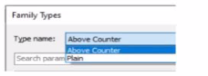
A family in a project contains the following types:
The following edits are made in the Family Editor and loaded into the project:
1. The type Plain is renamed to Standard
2 A new type is added named GFCI
Which types does this family now have in the project?
1. The type Plain is renamed to Standard
In Revit, when editing a family in the Family Editor and reloading it into a project, Revit handles type changes using specific update rules. Types that are renamed overwrite their earlier version in the project because they retain the same internal type ID. Types that are added to the family also appear in the project once reloaded.
Initially, the family contains two types:
Above Counter
Plain
The changes made in the Family Editor are: 1 Rename Plain Standard 2 Add a new type named GFCI
According to documented Revit behavior for type updates:
''When a family is reloaded into the project, any renamed family type replaces its previous version while maintaining its parameter assignments. Newly created types are added as additional family types available for placement within the project.''
Therefore:
Plain no longer exists because it was renamed
Standard now exists in its place
GFCI is added as a new family type
Above Counter remains unchanged
Thus, the family in the project now contains: Above Counter GFCI Standard
This matches answer choice: B. Above Counter, GFCI, Standard
Exhibit.
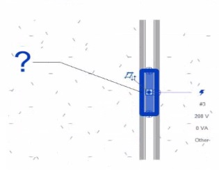
An electrical designer creates a panel schedule. Which Electrical Equipment parameter defines the default name of the panel schedule view?
In Autodesk Revit for Electrical Design, when a designer creates a panel schedule, the default name of the panel schedule view is automatically derived from the Panel Name parameter of the Electrical Equipment family to which the circuits are assigned.
According to the Revit MEP User's Guide (Electrical Systems section: Panel Schedules):
''When you create a panel schedule, Revit uses the Panel Name parameter of the electrical equipment to define the default schedule name. The Panel Name identifies the distribution panel that supplies the circuits. This name appears in both the Panel Schedule view and in circuit information tags.'' --- Revit MEP User's Guide, Chapter 17: Electrical Systems -- Panel Schedules
The Panel Name is a critical electrical equipment instance parameter located in the Electrical -- Circuiting group of properties. It appears in both the Electrical Equipment Properties Palette and the Panel Schedule Header. This name can later be modified manually, but by default, it directly controls the naming convention of the generated schedule.
In contrast:
A . Type Mark --- identifies types within the family for documentation and does not control schedule naming.
B . Mark --- a unique instance identifier often used for tags, but not for panel schedule view naming.
C . Description --- provides descriptive text only for documentation or labeling.
D . Panel Name --- correctly defines and drives the default schedule view name for panels and circuits.
When a panel (electrical equipment) is placed in the model and circuits are connected, Revit generates a new Panel Schedule View automatically titled using the value entered in the Panel Name field (e.g., ''Panel LP-1''). This ensures consistency between the modeled equipment and the schedule documentation.
Verified Reference Extracts from Revit for Electrical Design Documentation:
Autodesk Revit MEP User's Guide (2011), Chapter 17: Electrical Systems -- Creating and Editing Panel Schedules:
''The name of the panel schedule view is determined by the Panel Name property of the electrical equipment.''
Revit MEP Electrical Design Training Manual, Module: Electrical Equipment and Panel Schedules:
''Panel Name is used by Revit as the default identifier for any panel schedule view created for that equipment.''
An electrical designer is routing conduit through a building model to coordinate with other disciplines, the electrical designer wants to view selected components in a cropped 3D view.
With the conduit components selected, which tool should the designer use?
In Revit Electrical Design, the Selection Box tool is used to quickly isolate and display selected components in a cropped 3D view. When an electrical designer selects conduits or devices in a model and chooses Selection Box from the Modify tab, Revit automatically generates a 3D view bounded tightly around the selected elements, helping coordinate routing in confined or congested spaces.
According to the Revit MEP User's Guide under ''Creating 3D Views'':
''Use the Selection Box tool to create a 3D view that isolates selected elements. Revit automatically crops the view extents to the selected geometry.''
This feature is critical in multidisciplinary coordination because it allows the electrical designer to review specific conduits, cable trays, or lighting paths in context without manually adjusting view boundaries.
In contrast:
Default 3D View (Option B) shows the entire model.
Scope Box (Option C) controls view extents in 2D views or view templates, not instant isolation.
Section Box (Option D) is manually adjusted within an existing 3D view but does not automatically generate a cropped view around selected elements.
Therefore, the Selection Box is the correct and most efficient tool for this task.
References:
Autodesk Revit MEP User's Guide -- Chapter 47 ''Creating and Managing 3D Views,'' pp. 1108--1111
Smithsonian Facilities Revit Template User's Guide -- Section 3.6 ''Egress Routes and Coordination Views,'' p. 40
Autodesk Revit Electrical Design Essentials -- 3D Visualization and Coordination Techniques