Key details for this exam, checked against the published exam outline
Each question shows the correct answer and an explanation of why it is right
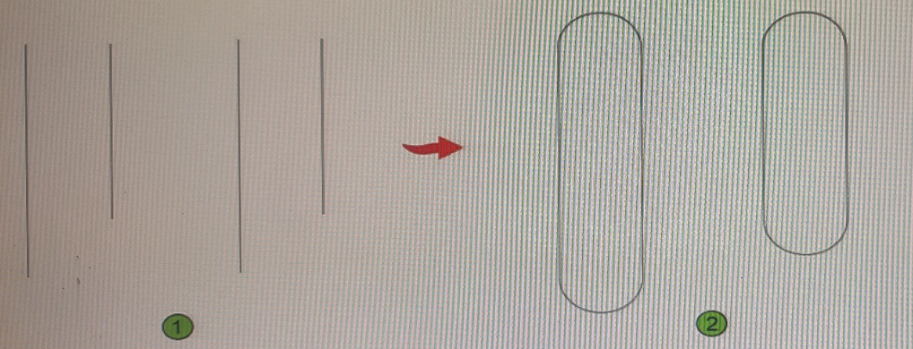
You need to convert the two sets of parallel lines shown in 1 into the objects shown in 2 without repeating the command.
What should you use?
A CAD designer is working on a project where the only drawing available is in POT format The designer imports the PDP into the drawing, but the text objects arc now polylines.
what needs to the done to convert the polylines to text objects.
Issue with PDF Text Objects:
When importing a PDF into AutoCAD, text objects may be converted to polylines.
This happens because AutoCAD interprets the text as vector graphics rather than editable text.
Conversion Process:
Option A: The Combine Text tool (TXT2MTXT) is used to combine multiple text objects into a single multiline text object. It does not convert polylines back to text.
Option C: The Edit Polyline (PEDIT) command and Join option are used to join polylines, not convert them to text.
Option D: The JOIN command is similar to PEDIT and is used for joining polylines.
Correct Tool:
Option B: The Recognize SHX Text tool (PDFSHXTEXT) is specifically designed to recognize text that has been converted to polylines during PDF import. It converts these polylines back into text objects.
Conclusion:
Use the Recognize SHX Text tool to select all polyline text objects and convert them back to editable text.
AutoCAD Knowledge Base on PDF Import and Text Recognition.
AutoCAD 2024 User Guide on PDF Import Tools.
Refer to exhibit.
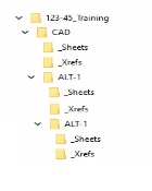
An alternate design option toider (ALT-1) is created with a copy of the original files.
The sheets for the alternate design should reference the drawings in the Al T-1 _Xrefs folder
To make sure that the host drawings in the ALT-1 drawings display the correct reference files without errors, which of the following settings should do applied to the xrefs?
Access the Xref Manager: Type XREF in the command line and press Enter.
Select the Xref: Choose the Xref you want to modify from the list.
Modify the Path: Click on the Path Type and select Make Relative. This ensures that the references will correctly point to the ALT-1_Xrefs folder relative to the current drawing location.
AutoCAD Help Documentation on Attach and Overlay External Reference
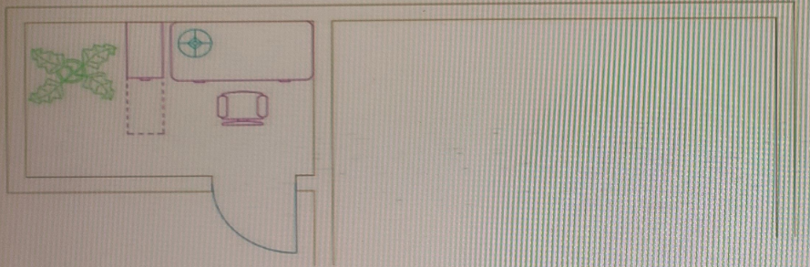
You have the office arrangement shown in exhibit 1. (Refer to the exhibit 1 tab.)
You need a mirror line to create the right-hand office arrangement shown in exhibit 2. (Refer to the exhibit 2 tab.)
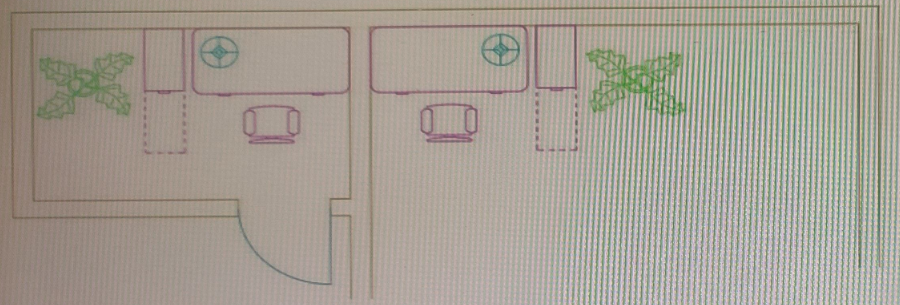
Which tool would you use to make sure the mirror line is centered between the two wall lines without adding additional linework?
One of the lines in the drawing is at a 30 degree angle. What's the quickest way to align the X-axis of the UCS to that line?
UCS is a command that sets a new user coordinate system (UCS) by specifying points or by selecting an object. You can use the Object option to align the UCS with a selected object such as a line.
You need to configure the layout viewports shown in the exhibit.
Which three methods can you use to create the viewports in a layout tab? (Select 3)
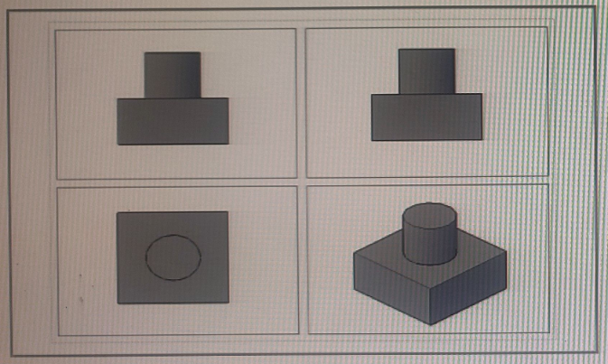
a layout viewport is a window that displays a view of model space on a layout tab. You can create multiple layout viewports to display different views of your model at different scales.
To create the viewports in a layout tab, you can use three methods:
From the Viewports dialog box: select a viewport configuration
Create individual viewports by using the MVIEW command
From the View Manager dialog box, generate named views and add them as layout viewpoints
These methods will allow you to create and arrange viewports on your layout tab.
Exam domains verified against: Official AutoDesk ACP-01101 exam guide, last checked September 2026.
Create and manage layers with properties, overrides, and filters. Set up user coordinate systems and manage their origin and rotation. Query and modify object properties using the Properties palette and MEASUREGEOM command. Customize the application interface and maintain drawing health using AUDIT, RECOVER, and purge tools.
Sample question from this domain above: Q2
Create and apply annotation and table styles. Manage drawing scales and annotative scaling for text, dimensions, leaders, and hatch. Add and position annotations such as multileaders, dimensions, and tables in designs and viewports.
Create and manage layout viewports including clipping, locking, and viewport scaling. Define and publish multiple drawing sheets using the PUBLISH command and eTransmit. Manage sheet sets and projects with the Sheet Set Manager or Project Manager to organize layouts and generate sheet list tables.
Create and manage layout viewports including clipping, locking, and viewport scaling. Define and publish multiple drawing sheets using the PUBLISH command and eTransmit. Manage sheet sets and projects with the Sheet Set Manager or Project Manager to organize layouts and generate sheet list tables.
Collaborate using shared drawing files and traces. Compare objects between drawing versions. Manage external references by attaching and overlaying xrefs, managing paths, and manipulating frames. Incorporate external data through PDF imports, data links, and dynamic fields.
Sample question from this domain above: Q6
Common questions about the exam itself

